
Project

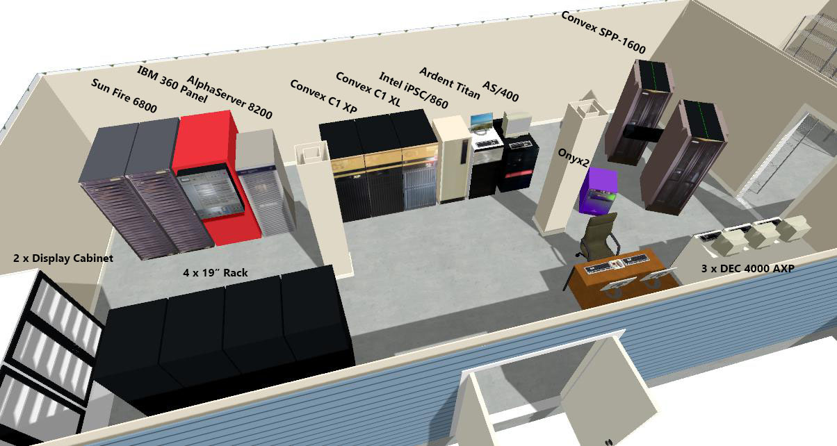
Part of the Vaxbarn collection is what could very well be the largest collection of Convex supercomputers in the world.
The Convex adventure started in 2016 with an eBay advertisement, and since then the collection has seen the addition of 9 Convex supercomputers, spanning three generations of machines.
- Details
https://www.youtube.com/watch?v=0EPrUIyD1m0
In this video, we describe how, thirty years later, we recreated a historically significant rendering of a vibrating L-Shaped Membrane in MATLAB 3.5, running on a 1987 Ardent Titan Graphics Supercomputer (TITAN-MATLAB).
- Details
Read more: Recreating the MATLAB vibrating membrane on the Ardent Titan
As if one project for the new year (New project: Eagle Emulator) isn't enough, I've also come to the conclusion that I need more space for the collection. Hence the proposed addition of a Large Systems Room to the VAXbarn.
- Details
*** UPDATED 24-APR-2017 ***
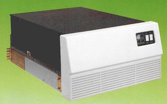
Almost a new year, time for a new project. Since the Convex C1 XP and Convex C1 XL I'm getting are missing their primary hard drive, I need to replace it with something. These systems are quite picky about what disks they support, but even if they weren't, working disks with an SMD (Storage Module Drive) interface are becoming somewhat rare. One disk I am sure these systems support is the Fujitsu M2351 ("Eagle") pictured above.
- Details
I have a TMS9900 based system on eurocards, FTI990 made by TEP. With this system, I have a copy of Eyring Research Institute's PDOS on floppy disks.
To save this OS, and to be able to share it with fellow TMS9900 enthousiasts, I have built a disk emulator for use with the FTI990, using my Digilent XUPV5 FPGA card.
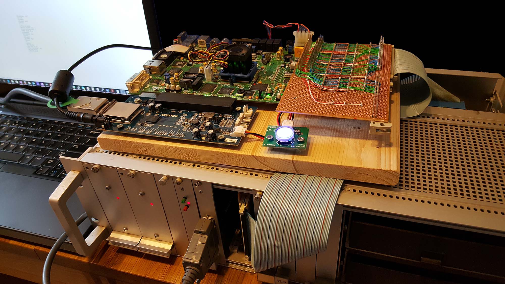
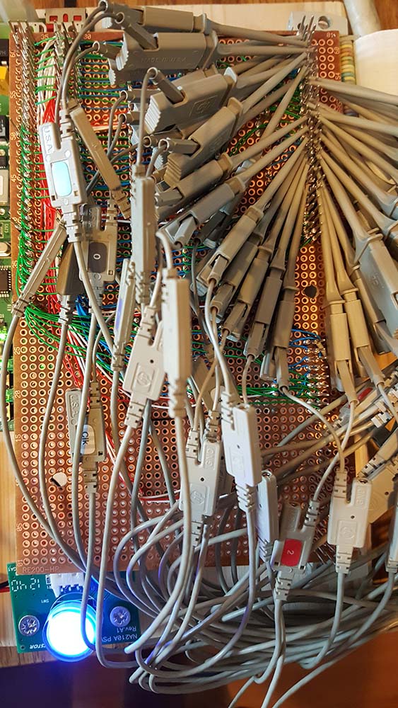
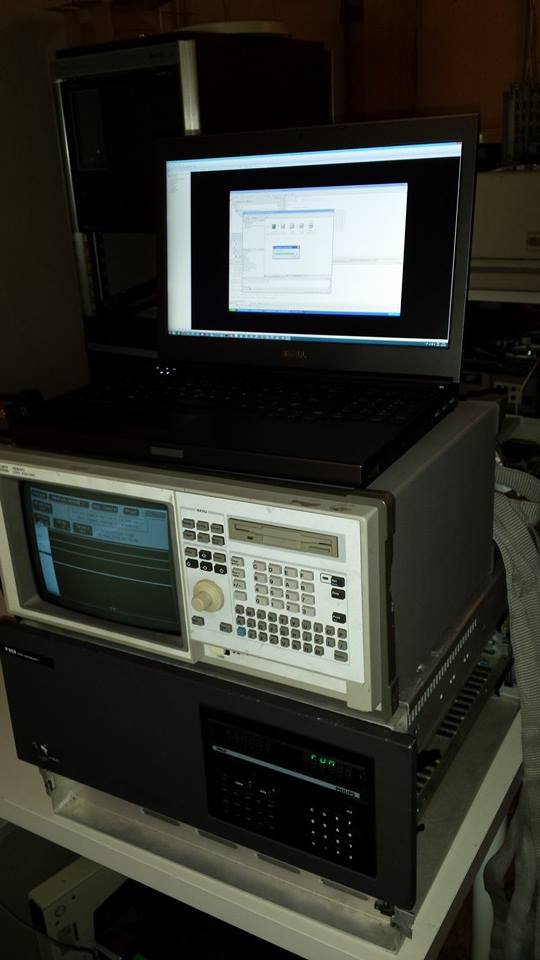
Emulator (mounted on wooden plank) on top of the FTI990 system. From the left top side, clockwise: XUPV5 FPGA card, wire-wrap board with level shifters to interface with 5V logic, card with bus buffer IC's plugged into the FTI990, PCIe interface to laptop.
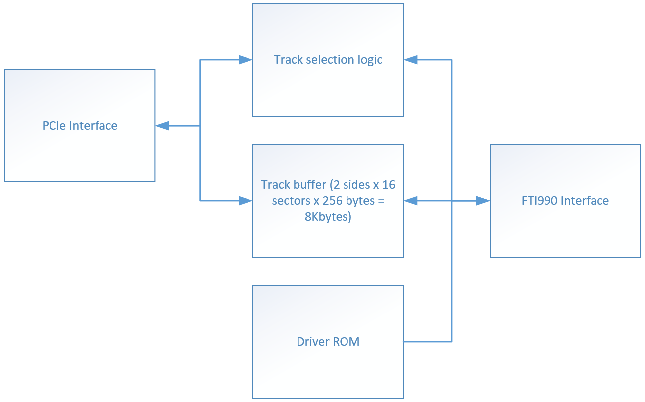
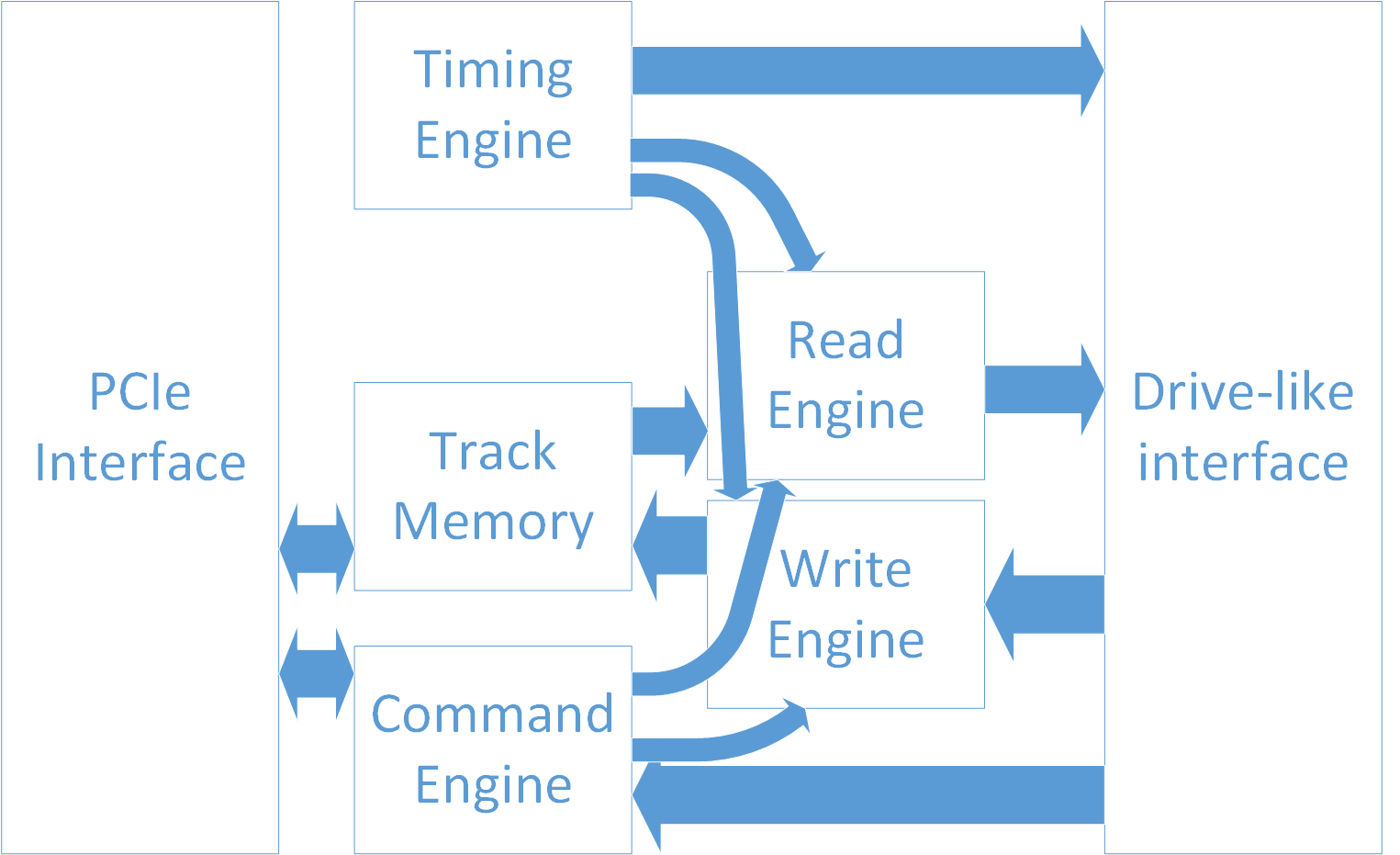
Above is a block diagram of the emulator: on the left is a PCIe interface to talk to the laptop used to capture the disk images. On the right is some logic to talk to the TMS9900 bus.
The emulator works as follows: part of the Boot ROM in the FTI990 is a table with four pointers to Boot-ROM provided disk device drivers; in my boot ROM, only the first pointer points to an actual driver, for that for the floppy disc controller. The other three pointers point to a table that indicates "no device here". When the FPGA sees a memory read transaction on the TMS9900 bus to read the second pointer in the table, it hijacks the bus to change the value read from the Boot ROM. It can do so, because the bus is held high with resistors, and pulled low by open-collector TTL logic outputs. This means that even though another device on the bus (the boot ROM) is already responding to that read transaction, we can change 1's into 0's in the read value by pulling those bits low. In this manner, we change the second pointer from F83A to E800.
      +----------+
>0000 |          |
      |          |
      |   RAM    |
      |          |
>DFFF |          |
      +----------+
>E000 |          |  >E100->E1FF : sector buffer (256 bytes)
      | Devices  |  >E200->E201 : sector# register (write) / status register (read)
      |          |  >E202->E203 : single/double sided register
>EFFF |          |  >E800->E8FF : driver ROM
      +----------+
>F000 |          |
      | Boot ROM |  >FC2A->FC2B : hijacked driver pointer
>FFFF |          |
      +----------+
At address >E800 (in TMS 9900 assembly, '>' is the prefix for hexadecimal values), our emulator provides a driver for the emulated disk. when reading or writing a sector, the driver sends the sector# (logical block address) of the required sector to a sector# register at >E200. Then waits for that sector to become available in the buffer. If needed, the program running on the laptop will save the track that was previously in the buffer, and then load the buffer with the requested track. Once the status register indicates that the sector is available, the driver will copy the data to or from the 256-byte sector buffer located at >E100. Whenever sector 0 is read or written, the driver looks at the single/double-sided flag in that sector, and writes it to the single/double sided register at >E202. This is important, because when booting, the disk is always read in single-sided mode, even if it's a double-sided disk. Booting starts by reading a number of sectors from the disk, starting at sector 1136. Because the disk is treated as single-sided, sector 1136 is on track 71, not on track 35. However, after sector 0 is read, if it's a double-sided disk, whenever PDOS addresses sector 1136, we want to access track 35.
On the laptop, we continuously poll two registers on the PCIe side; one is the "current generation number" register. Every time a sector is written to by the FTI990, the value in this register increments by one. The software on the laptop keeps track of the generation number, and when it changes, it knows it has to read the track data back from the track buffer to keep it's disk image up to date. Once that's done, it writes the updated generation number to the "last seen generation number" register. The second register that's read is the "wanted track" register. If it's different from the track currently loaded in the track buffer, the software will write the requested track to the track buffer, then update the "loaded track" register.
The emulator will tell the FTI990-side driver that it's busy when either the "wanted track" doesn't match the "loaded track", or when the "current generation number" doesn't match the "last seen generation number".
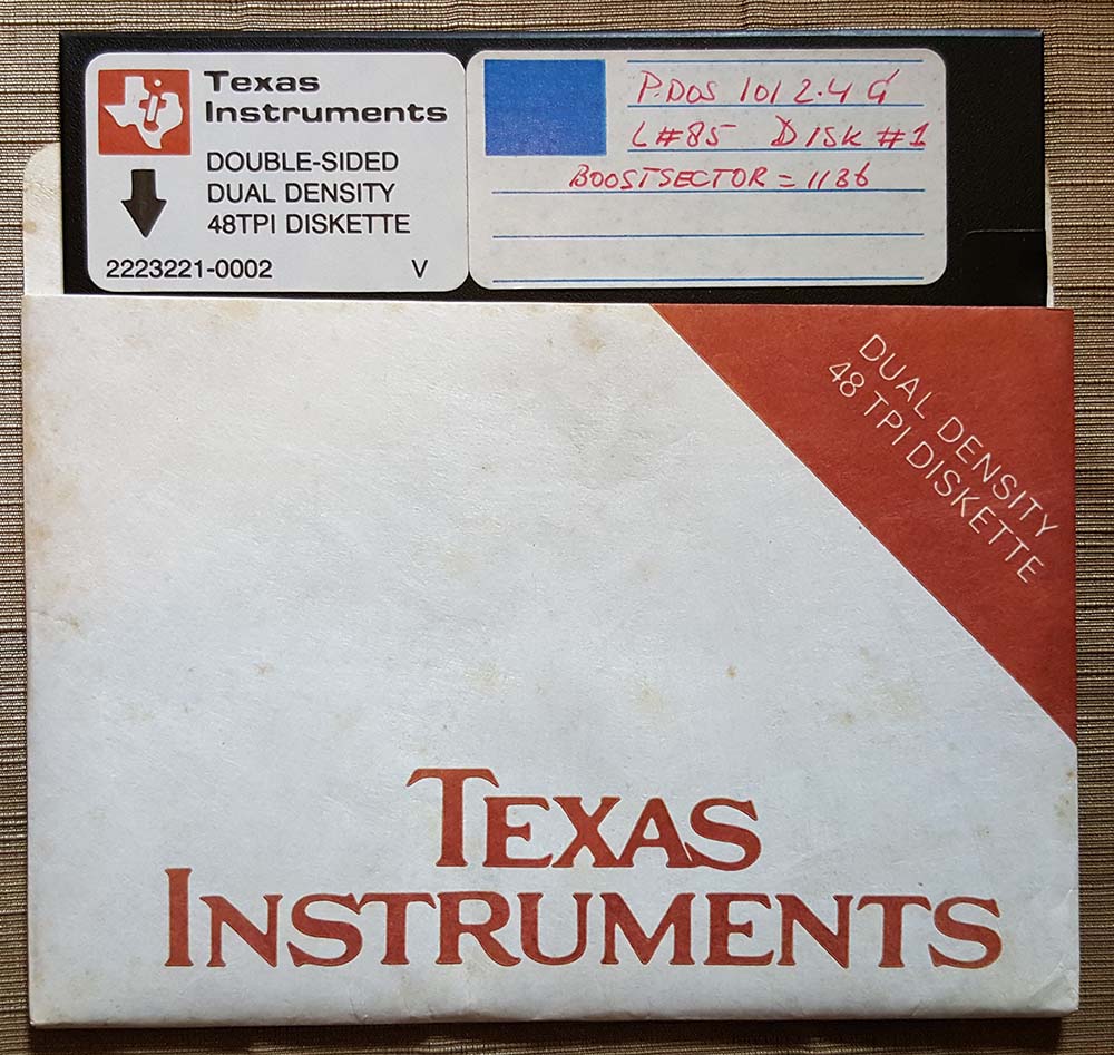
PDOS boot floppy
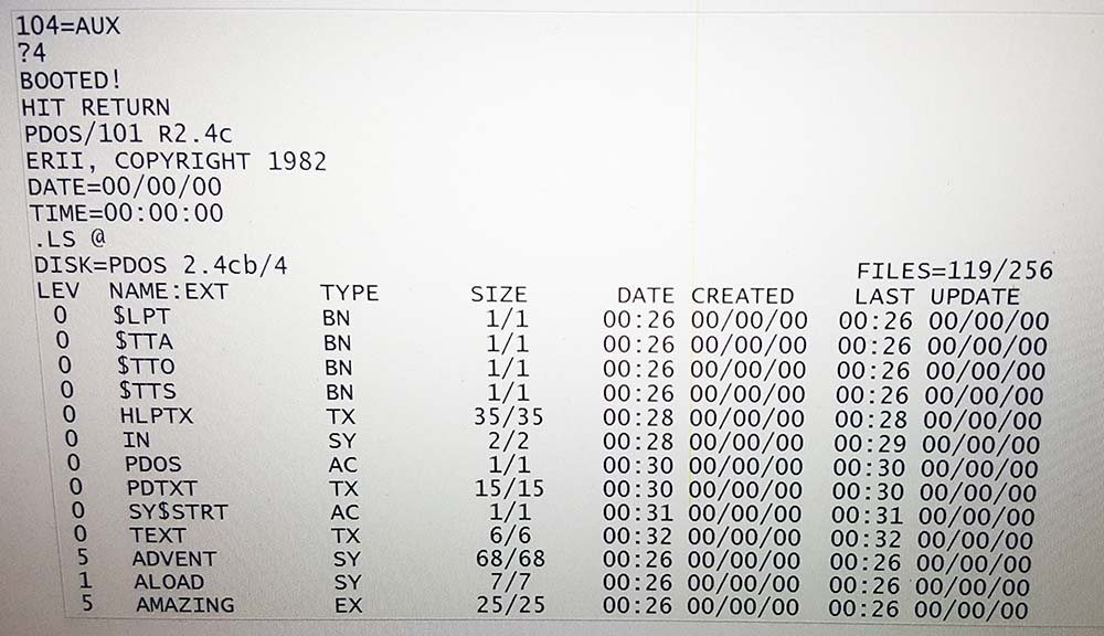
PDOS 2.4 booting from the emulated disk
Emulator with test leads for debugging (with a logic analyzer)
Finally, here is the driver code as contained in the ROM:
                        ; -------------------------------------
                        ; Driver linkage table
                        ;--------------------------------------
E800    100D                     JMP    INIT        ; init vector
E802    1010                     JMP    READ        ; read vector
E804    1014                     JMP    WRIT        ; write vector
E806    100D                     JMP    MOFF        ; motor-off vector
E808    0470                     DATA   >1136       ; boot sector
E80A    0470                     DATA   >1136
E80C    0470                     DATA   >1136
E80E    0470                     DATA   >1136
E810    4645 4939 3930           TEXT   "FTI990-EMU"
        2D45 4D55
E81A    0000                     BYTE   >00
                        ; -------------------------------------
                        ; Initialization routine
                        ;--------------------------------------
E81C    04E0 E202       INIT:    CLR    @>E202         ; Clear double-sided register
E820    045B                     RT
                        ; -------------------------------------
                        ; Periodic routine
                        ;--------------------------------------
E822    045B            MOFF:    RT
                        ; -------------------------------------
                        ; Read sector routine
                        ;--------------------------------------
E824    C06D 0004       READ:    MOV    @4(R13),R1     ; destination: memory
E828    0202 E100                LI     R2, >E100      ; source: sector buffer
E82C    1004                     JMP    COMN           ; continue with read/write common code
                        ; -------------------------------------
                        ; Write sector routine
                        ;--------------------------------------
E82E    C0AD 0004       WRIT:    MOV    @4(R13),R2     ; source: memory
E832    0201 E100                LI     R1, >E100      ; destination: sector buffer
                        ; -------------------------------------
                        ; Common read/write code
                        ; -------------------------------------
E836    C020 E200       COMN:    MOV    @>E200, R0     ; ready ?
E83A    11FD                     JLT    COMN           ; no; wait
E83C    C82D 0002 E200           MOV    @2(R13),@>E200 ; request sector
E842    C020 E200       SEEK:    MOV    @>E200, R0     ; ready ?
E846    11FD                     JLT    SEEK           ; no; wait
E848    1304                     JEQ    DOIT           ; ready, no error; continue
E84A    0200 0065                LI     R0, >101       ; error; return error #101 (invalid track number)
E84E    0460 E870                B      RETN
E852    0200 0080                LI     R0, 128        ; number of words to copy
E856    CC72            COPY:    MOV    @R2+, @R1+     ; copy 1 word
E858    0600                     DEC    R0             ; are we done?
E85A    16FD                     JNE    COPY           ; no; copy next word
E85C    C02D 0002                MOV    @2(R13), R0    ; yes; sector is zero?
E860    1605                     JNE    SUCC           ; no; we're done
E862    C06D 0004                MOV    @4(R13), R1    ; yes, get address of buffer
E866    C821 001E E202           MOV    @30(R1), >E202 ; copy double-sided flag from sector buffer to double sided register
E86C    04C0            SUCC:    CLR    R0             ; indicate success
E86E    05CE                     INCT   R14            ; increment return address by two (no error)
E870    04E0 2FE8       RETN:    CLR    @L3LOCK        ; clear OS lock
E873    0380                     RTWP                  ; return to OS
- Details
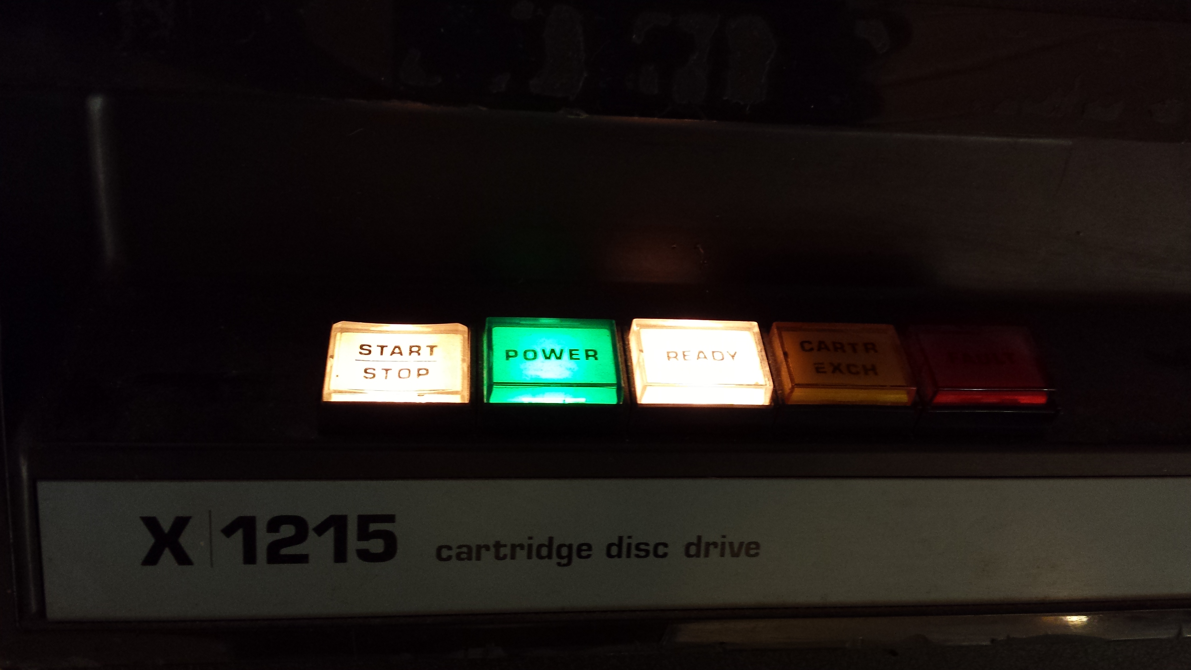
I have the following X1215 disk packs (23 in total) in my collection.
Imaged
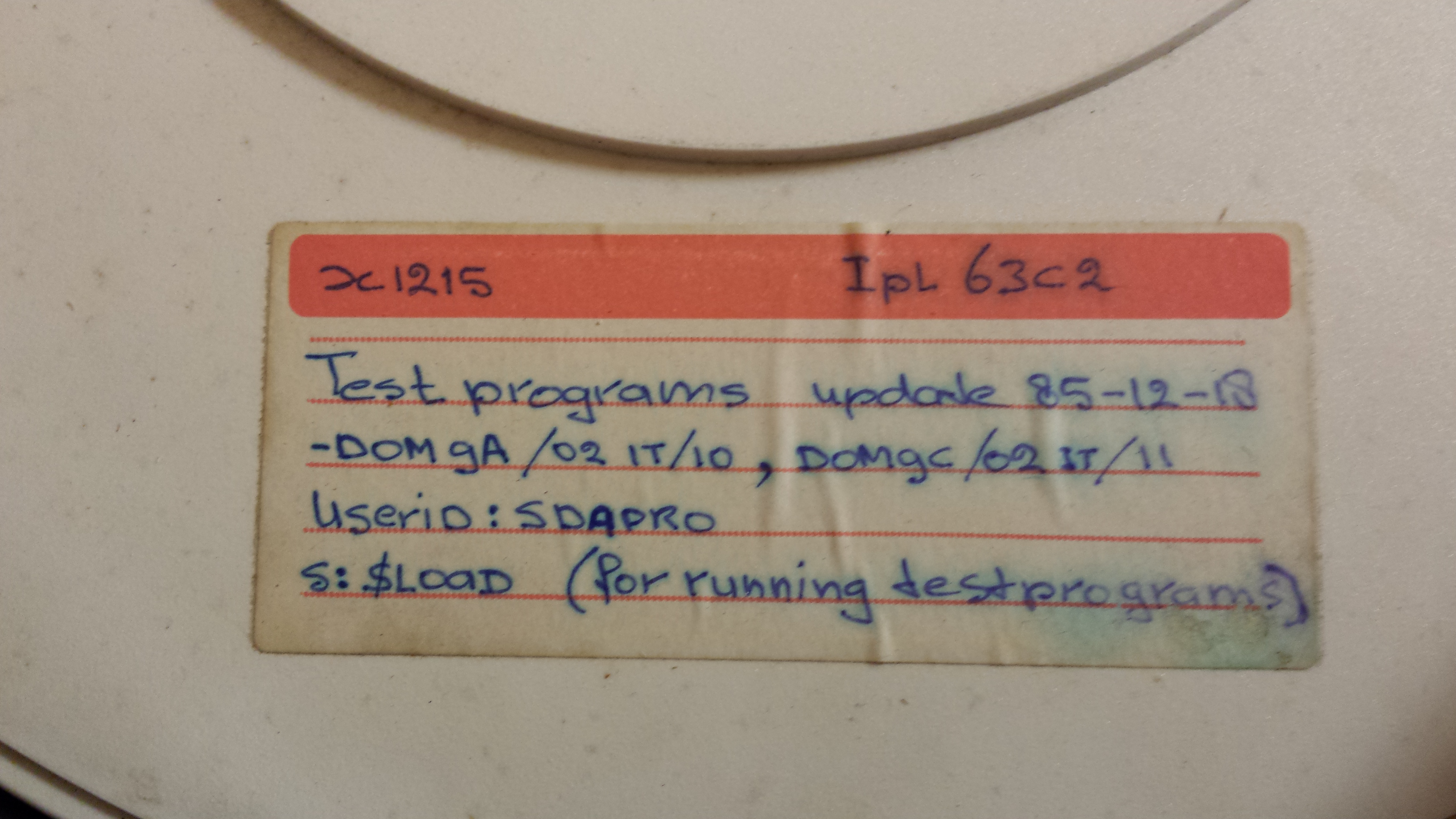
- X1215 IPL 63C2
Testprograms update 85-12-18
DOM9A/02 IT/10, DOM9C/02 IT/11
Userid: SDAPRO
s:$load (for running testprograms) [Internal label: TP09; Does indeed contain test programs] - P800 (X1215) [Internal Label: ECA58; Contains games]
- SAG3
KERNEL 3
MULTIBASIC [Internal label: DJO-PACK; Contains development tools (BASIC, Assembler,...)] - DOM 210 & 211 for X1215
update P800 testprograms
27-09-'84 R.v.d.Heyden [Internal label: RINUS; Contains test programs] - TP00 Test Pack [Internal label: RINUS; Contains test programs + other stuff (eg ISCOS100 stuff)]
- PHILIPS unlabeled [Internal label: TP0; Contains test programs]
- CPU ISCOS 70
4022 250 0004.1
PAB nr 8122 141 0470.1
BD83 [Test or Manufacturing Data For Philips ISCOS 70 PLC CPU] - Ext Mem Mod 286
4022 226 2340.1
PAB nr 8122 141 0456.1
BD82 [Test or Manufacturing Data] - VIP V12
4311 027 1629.1
PAB nr 8122 141 0277.1
BD51 [Test or Manufacturing Data] - DISK Unit 1 [Internal label: ECA59]
- TRAINING 004
P.H.Kraaijeveld [Internal label: TRAINING] - FPP KENIA [Formatted Empty pack]
- 4 x PHILIPS unlabeled [Formatted Empty pack]
- MEMOREX unlabeled [Formatted Empty Pack]
- 2 x CDC unlabeled [Unformatted Empty pack]
Problems
- DOM_HARRY OLDREL
old sources of release 01-10-82 [Lots of bad spots] - Graphics 8P-A
4022 226 3470.1
PAB nr 8122 141 0286.1
BD58 [Many read problems] - Service pack 1
various programmes [Reads OK, but weird file system structure issues] - X1216 IPL 63C2
Test programs update 85-12-18
-DOM9 A/02 IT/10 FL/03 IT/11 [Test or Manufacturing Data]
Userid: SDAPRO
s:$LOAD [X1216 Pack] - DOM 811 adr/02 intr/11
terminal adr/10 intr/6
update test programs 27-09-84
IPL/65C2 [X1216 Pack] - LAB Backup [X1216 Pack]
- TEST TP1
R=0002 [X1216 Pack]
- Details
The X1215 drive imaging system is now working properly, and I have successfully created disk images for two disk packs.
First I had to fix the drive to start at track 0, as it should. Before, it started at track 4. Fortunately, on the x1215 you can change which track is seen as track 0 by moving the optical zero sensor. That means that the meander tracks used for positioning can remain in place so you don't lose alignment.
After that, I let the drive create images for each track, which were then analyzed. The resulting disk image looked ok for the first disk, labeled "FPP Kenia", which turned out to be a blank, formatted disk. The second disk, labeled "Testprograms" also seemed ok at first sight, but the resulting disk image was still wrong, as booting it produced a hang in Theo Engel's P856 emulator. It turned out that the data for the two heads (0 and 1) was the same on each track.
Some debugging with the logic analyzer showed that the head-select and address-bus lines were correctly getting asserted to change the read head, and that these signals correctly reached the DC logic card in the drive, but that the head-select lines from the DC card didn't change as a result. The problem turned out to be a flip-flop (half of a 7474 IC) on the DC card, so once this was replaced, I took another image of the "Testprograms" disk.
As the header shows, this disk pack was written in 1982 (not 1985 like it says on the label). 32 years later I can still read the data:
==============================================
PHILIPS P800 X1215 CARTRIDGE DISC DRIVE READER
==============================================
(c) Copyright 2014 by C. Vanderhoeven

DSK-I-LABEL: Sector offset determined to be 1. Disk label:
     0000 0000 2020 2020 414c 4542 204c 203d 5054 3930         LABEL = TP09
     2020 2020 2020 2020 2020 2020 2020 4144 4554 3d20               DATE =
     2020 3130 2020 3630 2020 3238 2020 3231 3531 4150   01  06  82  1215PA
     4b43 4e20 5242 3d20 2020 3030 3530 0200 1000 0300 CK NBR =  0005
     9a01 0500 6400 0000 0000 0000 0000 0000 0000 0000      d
     0000 0000 0000 0000 0000 0000 0000 0000 0000 0000
     0000 0000 0000 0000 0000 0000 0000 0000 0000 0000
     0000 0000 0000 0000 0000 0000 0000 0000 0000 0000
     0000 0000 0000 0000 0000 ff7f ffff ffff ffff ffff
     ffff ffff ffff 0000 0000 0000 0000 0000 0000 0000
     0000 0000 0000 0000 0000 0000 0000 0000 0000 0000
     0000 0000 0000 0000 0000 0000 0000 0000 0000 0000
     0000 0000 0000 0000 0000 0000 0000 0000 0000 0000
     0000 0000 0000 0000 0000 0000 0000 0000 0000 0000
     0000 0000 0000 0000 0000 0000 0000 0000 0000 0000
     0000 0000 0000 0000 0000 0000 0000 0000 0000 0000
     0000 0000 0000 0000 0000 0000 0000 0000 0000 0000
     0000 0000 0000 0000 0000 0000 0000 0000 0000 0000
     0000 0000 0000 0000 0000 0000 0000 0000 0000 0000
     0000 0000 0000 0000 0000 0000 0000 0000 0000 0000
     0000 0000 0000 0000 0000
This time, the disk image works! I can boot it in Theo's emulator, and I get the following little dialog going (what I typed in bold):
MONITOR ? DOM9A

LOAD ADDRESS: 0000
**DOS 09 ** 8701 312 84000 *‼

 DATE :

 TIME :

 BATCH PROCESSING ? N

USERID: SDAPRO
S:LSD
LABEL = TP09              DATE =  01  06  82  1215PACK NBR =  0005‼
*********LIBRARY DIRECTORY*********‼
****FILENAME****TYPE****ADDRESS****‼
    BPTR1       LM      0540‼
    BSER1       LM      0560‼
    BCR1        LM      0578‼
    BDIOD1      LM      0588‼
    BCASS1      LM      0598‼
    BCDD1       LM      05B8‼
    BMAGT1      LM      05D8‼
    BDISP1      LM      05F0‼
    BCDC2       LM      0608‼
    BMAGT2      LM      0630‼
    BSLCU2      LM      0648‼
    B-ALCU      LM      06B0‼
    BMA8AC      LM      0710‼
    BLSM16      LM      0748‼
    BV28CM      LM      0798‼
    BHDLC       LM      07F0‼
    BZSAC1      LM      0828‼
    BSLCU4      LM      0850‼
    BPTP1       LM      08B0‼
    BLP1        LM      08D0‼
    CPA4K1      LM      08F0‼
    CPA4K2      LM      09E8‼
    CPA8K       LM      0A90‼
    BMEMO       LM      0AB8‼
    BBMMU1      LM      0AC0‼
    BBFPP1      LM      0AD8‼
    BPRTC1      LM      0AE8‼
    BRAM        LM      0AF8‼
    CPB8K       LM      0B00‼
    CPZ8K       LM      0B30‼
    BBMEMO      LM      0B60‼
    BFLOP1      LM      0B70‼
    BBDISP      LM      0BA0‼
    BP817       LM      0BB0‼
    BFHD1       LM      0BE0‼
    BZ1250      LM      0BF0‼
    IPLC1       LM      0C08‼
    BBRAM       LM      0C20‼
    BATYPE      LM      0C38‼
    BBSER1      LM      0C40‼
    BZSCU       LM      0C50‼
    BX1216      LM      0C68‼
    BZ1216      LM      0C88‼
    BZCDD1      LM      0CA8‼
    SBCA        LM      0CC8‼
    CP1A        LM      0CE0‼
    CP57RE      LM      0D10‼
    REMMU1      LM      0D48‼
    REPAF       LM      0D68‼
    BF1MZ       LM      0D88‼
    BF1MB       LM      0DB0‼
    BVCCU4      LM      0DD8‼
    BASCU4      LM      0E08‼
    BACCZ       LM      0E28‼
    PRORAM      LM      0E40‼
    BZTTY1      LM      0E48‼
    FLCOPY      LM      0E60‼
    COPY        LM      0E78‼
    ADJUST      LM      0EA8‼
    BIGD2S      LM      0EC0‼
    EFPP1       LM      0EF0‼
    BIGD2C      LM      0F10‼
    BWDAB1      LM      0F38‼
    BHLVCU      LM      0F78‼
    WDDU        LM      0FB8‼
    WDABU       LM      0FF8‼
    BSLCUZ      LM      1040‼
    CP1/2B      LM      1070‼
    MMU2B       LM      10D8‼
    PAF2B       LM      10F0‼
    BWDD1       LM      1110‼
    BWDH1       LM      1140‼
    SCSISH      LM      1180‼
    BWJA1       LM      1190‼
    IOPZR       LM      11F0‼
    ID12NC      UF      11F8‼
    INDICE      UF      1208‼
    GENT1       UF      1240‼
    GENT2       UF      1248‼
    GENT3       UF      1250‼
    GENT4       UF      1258‼
    GENT5       UF      1260‼
    GENT6       UF      1268‼
    GENT7       UF      1270‼
    GENF1       UF      1278‼
    GENF2       UF      1280‼
    GENF3       UF      1288‼
    GENF4       UF      1290‼
    GENF5       UF      1298‼
    GENF6       UF      12C0‼
    GENF7       UF      12C8‼
    GENF8       UF      12D0‼
    GENF9       UF      12D8‼
    GENF10      UF      12E0‼
    GENF11      UF      12E8‼
    GENF12      UF      12F0‼
    MEMTS1      LM      12F8‼
    BELUNI      LM      1310‼
    BDIPA       LM      1348‼
    INTER       LM      1358‼
    WDEU        LM      1360‼
    STRIMR      LM      13A8‼
    BHLX        LM      13E8‼
    WDHU        LM      1400‼
    BWDE1       LM      1448‼
    BAMA4Z      LM      1480‼
    BWMF1       LM      14C8‼
    BCIPH1      LM      14E8‼
S:$LOAD
RUN 0‼

  LOADER OF STAND ALONE TEST PROGRAMS 82 11 22
  DOS 04/6/9
  PROGRAM NAME TO BE LOADED : CPA8K

  THE 12 NC NUMBER OF THE LOADED PROGRAM IS :     5111 199 74512
Execution stopped with a HLT

Run/Boot: emulation stopped at address  02FC
90203587 instructions in 125.605228 seconds: 718151 instructions per second
As you can see, there are a lot of different test programs there.
Reading and decoding a disk pack takes me a while. The steps involved are:
- Carefully checking the disk pack for dust and damage using a flashlight
- Spinning up the disk pack in a second X1215 (with faulty electronics and no heads) and letting it spin for an hour or so to get rid of any dust
- A second inspection of the disk pack for any remaining dust
- Mounting the disk pack on the X1215 used for imaging
- Spinning up the disk
- Start the imaging program like this:
C:\> X1215 cartridge tp09
- If the imaging program aborts because of an UNSAFE condition on the drive, spin down the disk and spin it up again (to clear the condition), then restart the imaging program to restart at the track at which the error occurred, like this:
C:\> X1215 cartridge tp09 154-203
- Repeat the last step until the entire disk has been imaged, you now have a list of files named tp09_ttt_h.img where ttt is the track number and h is the head number
- Start the analysis program to compile the disk image, like this:
C:\> X1215 decode tp09 tp09.img
- If there are no disk errors reported, we're done, and you can spin down and unload the disk; otherwise, continue
- The analysis program spits out a list at the end with tracks that have errors on them, like this:
****************************************
***
***   ERRORS IN TRACKS:
***   36-41,68,203
***
****************************************
- Start the imaging program to read these tracks again, like this:
C:\> X1215 cartridge tp09 36-41,68,203
- Go back to step 9 and repeat until you're satisfied with the error list.
NOTE: There may still be errors in the list at this point, because the disk may really have bad tracks or sectors. Tracks 200 - 203 are spare tracks that the operating system uses to map bad tracks to.
As you can imagine, this takes a while, but it is very rewarding to see the error list dwindle down to almost nothing. The end result of the entire operation may look something like this:
C:\src\x1215_reader\driver\Release>X1215 d aa tp09.img

==============================================
PHILIPS P800 X1215 CARTRIDGE DISC DRIVE READER
==============================================
(c) Copyright 2014 by C. Vanderhoeven

DSK-I-LABEL: Sector offset determined to be 1. Disk label:
     0000 0000 2020 2020 414c 4542 204c 203d 5054 3930         LABEL = TP09
     2020 2020 2020 2020 2020 2020 2020 4144 4554 3d20               DATE =
     2020 3130 2020 3630 2020 3238 2020 3231 3531 4150   01  06  82  1215PA
     4b43 4e20 5242 3d20 2020 3030 3530 0200 1000 0300 CK NBR =  0005
     9a01 0500 6400 0000 0000 0000 0000 0000 0000 0000      d
     0000 0000 0000 0000 0000 0000 0000 0000 0000 0000
     0000 0000 0000 0000 0000 0000 0000 0000 0000 0000
     0000 0000 0000 0000 0000 0000 0000 0000 0000 0000
     0000 0000 0000 0000 0000 ff7f ffff ffff ffff ffff
     ffff ffff ffff 0000 0000 0000 0000 0000 0000 0000
     0000 0000 0000 0000 0000 0000 0000 0000 0000 0000
     0000 0000 0000 0000 0000 0000 0000 0000 0000 0000
     0000 0000 0000 0000 0000 0000 0000 0000 0000 0000
     0000 0000 0000 0000 0000 0000 0000 0000 0000 0000
     0000 0000 0000 0000 0000 0000 0000 0000 0000 0000
     0000 0000 0000 0000 0000 0000 0000 0000 0000 0000
     0000 0000 0000 0000 0000 0000 0000 0000 0000 0000
     0000 0000 0000 0000 0000 0000 0000 0000 0000 0000
     0000 0000 0000 0000 0000 0000 0000 0000 0000 0000
     0000 0000 0000 0000 0000 0000 0000 0000 0000 0000
     0000 0000 0000 0000 0000

DSK-I-SECZERO: Sector 0 to be found at: 81572 1333359 2585078 3836955
TRK-W-DUPL: Same data on both heads in track 23
TRK-W-SECDIF: 36/0 can't handle sector difference of 2817287
TRK-W-DUPL: Same data on both heads in track 52
TRK-W-DUPL: Same data on both heads in track 55
TRK-W-DUPL: Same data on both heads in track 62
SEC-W-NODATA: No valid sector data found for sector 68/1/0
SEC-W-NODATA: No valid sector data found for sector 68/1/1
SEC-W-NODATA: No valid sector data found for sector 68/1/2
SEC-W-NODATA: No valid sector data found for sector 68/1/3
SEC-W-NODATA: No valid sector data found for sector 68/1/4
SEC-W-NODATA: No valid sector data found for sector 68/1/5
SEC-W-NODATA: No valid sector data found for sector 68/1/6
SEC-W-NODATA: No valid sector data found for sector 68/1/7
SEC-W-NODATA: No valid sector data found for sector 68/1/8
SEC-W-NODATA: No valid sector data found for sector 68/1/9
SEC-W-NODATA: No valid sector data found for sector 68/1/10
SEC-W-NODATA: No valid sector data found for sector 68/1/11
SEC-W-NODATA: No valid sector data found for sector 68/1/12
SEC-W-NODATA: No valid sector data found for sector 68/1/13
SEC-W-NODATA: No valid sector data found for sector 68/1/14
SEC-W-NODATA: No valid sector data found for sector 68/1/15
TRK-W-DUPL: Same data on both heads in track 142
TRK-W-DUPL: Same data on both heads in track 170
TRK-W-DUPL: Same data on both heads in track 176
SEC-W-NODATA: No valid sector data found for sector 203/0/0
SEC-W-NODATA: No valid sector data found for sector 203/0/1
SEC-W-NODATA: No valid sector data found for sector 203/0/2
SEC-W-NODATA: No valid sector data found for sector 203/0/3
SEC-W-NODATA: No valid sector data found for sector 203/0/4
SEC-W-NODATA: No valid sector data found for sector 203/0/5
SEC-W-NODATA: No valid sector data found for sector 203/0/6
SEC-W-NODATA: No valid sector data found for sector 203/0/7
SEC-W-NODATA: No valid sector data found for sector 203/0/8
SEC-W-NODATA: No valid sector data found for sector 203/0/9
SEC-W-NODATA: No valid sector data found for sector 203/0/10
SEC-W-NODATA: No valid sector data found for sector 203/0/11
SEC-W-NODATA: No valid sector data found for sector 203/0/12
SEC-W-NODATA: No valid sector data found for sector 203/0/13
SEC-W-NODATA: No valid sector data found for sector 203/0/14
SEC-W-NODATA: No valid sector data found for sector 203/0/15
SEC-W-NODATA: No valid sector data found for sector 203/1/0
SEC-W-NODATA: No valid sector data found for sector 203/1/1
SEC-W-NODATA: No valid sector data found for sector 203/1/2
SEC-W-NODATA: No valid sector data found for sector 203/1/3
SEC-W-NODATA: No valid sector data found for sector 203/1/4
SEC-W-NODATA: No valid sector data found for sector 203/1/5
SEC-W-NODATA: No valid sector data found for sector 203/1/6
SEC-W-NODATA: No valid sector data found for sector 203/1/7
SEC-W-NODATA: No valid sector data found for sector 203/1/8
SEC-W-NODATA: No valid sector data found for sector 203/1/9
SEC-W-NODATA: No valid sector data found for sector 203/1/10
SEC-W-NODATA: No valid sector data found for sector 203/1/11
SEC-W-NODATA: No valid sector data found for sector 203/1/12
SEC-W-NODATA: No valid sector data found for sector 203/1/13
SEC-W-NODATA: No valid sector data found for sector 203/1/14
SEC-W-NODATA: No valid sector data found for sector 203/1/15
TRK-W-DUPL: Same data on both heads in track 203

****************************************
***
***   ERRORS IN TRACKS:
***   36,68,203
***
****************************************

****************************************
***
***   DUPLICATES IN TRACKS:
***   23,52,55,62,142,170,176,203
***
****************************************
In this example, track 36 should be re-imaged, as there's a large gap where no data was read. Track 68 head 1 is a genuine bad track that has been replaced, and track 203 simply isn't there (it would seem that some older X1215's can only write 203 tracks rather than 204).
The duplicates indicated mean that the data on heads 0 and 1 is identical for that track. That check was added when I had the head-selection problem described earlier. In this case, it's probably valid, as you would expect to see this if all sectors in these tracks are empty (all zeroes)
- Details
The X1215 imager project has been completed to the point were I can now read data from the disk. The drive mechanism is not too stable (the heads may drift away, resulting in an UNSAFE condition), so I've chosen to image disk packs as separate images for each track, to make it easy to restart without having to redo everything. As the disks have 204 tracks on each side, this results in 408 files of half a megabyte each. The disk images contain the raw data as delivered by the disk, sampled at 50 MHz. That's 20 bits of sampling data for each bit cell. The track image is made during three full revolutions of the disk, so there should be 3 copies of each sector in each file. That way, if one copy is bad, another copy may have the correct data.
I've written a second program that takes one of these image files, and tries to recover the data from it. It will try to separate the data from the inter-sector gaps, and then analyze each sector to find the preamble (a lot of '0's followed by a single '1' to mark the beginning of the sector), the sector data (205 16-bit words), and the checksum word. If the checksum word matches the calculated checksum (XOR of each data word), the sector is good. If not, the backup copies are tried.
The output is presented like this:
ANALYZE SECTOR 14
340 bit preamble after 0 bits of crud
XOR: 6c9b LRC: 6c9b
0003 018e 2043 4f4e 5452 4f4c 2d53 5441 5455 5320      CONTROL-STATUS
4152 4541 2028 2f44 4354 2920 004c 0168 003c 0050 AREA (/DCT)  L h < P
2020 2020 2020 2020 2044 4154 4120 2020 2030 2020          DATA    0
2020 2020 2020 2020 2020 2020 2044 5754 4154 543a              DWTATT:
2041 5454 4143 4820 4c4f 4341 5449 4f4e 004d 0024  ATTACH LOCATION M $
003e 0050 2020 2020 2020 2020 2044 4154 4120 2020  > P         DATA
2032 3320 2020 2020 2020 2020 2020 2020 2044 5754  23              DWT
5353 543a 204c 4556 454c 2d23 2028 474e 494d 4f4e SST: LEVEL-# (GNIMON
2920 004d 0064 0006 0050 2a20 004d 00a6 0014 0050 )  M d   P*  M     P
2a20 2020 4457 5420 464f 5220 5050 3330 004d 00b0 *   DWT FOR PP30 M
0006 0050 2a20 004d 00c8 0038 0050 443a 5050 3330    P*  M   8 PD:PP30
2020 2044 4154 4120 2020 2027 5050 2720 2020 2020    DATA    'PP'
2020 2020 2020 2044 5754 444e 203a 2044 4556 4943        DWTDN : DEVIC
452d 4e41 4d45 004d 00d2 003c 0050 2020 2020 2020 E-NAME M   < P
2020 2044 4154 4120 2020 202f 3330 2020 2020 2020    DATA    /30
2020 2020 2020 2044 5754 4441 203a 2044 4556 4943        DWTDA : DEVIC
452d 4144 4452 4553 5320 004d 010e 0040 0050 2020 E-ADDRESS  M   @ P
2020 2020 2020 2044 4154 4120 2020 2038 3020 2020        DATA    80
2020 2020 2020 2020 2020 2044 5754 424c 473a 2042            DWTBLG: B
4553 5420 5245 434f 5244 204c 454e 4754 4820 004d EST RECORD LENGTH  M
014e 4e3a 0000 0000 0000                           NN:
This is already looking pretty decent. There's a slight problem, however. The first track read should be track 0, but it's not. The first track read appears to be track 2, so I'm missing the first two tracks. That means adjusting the head position, which I'm not very keen on doing, as I haven't got the proper alignment packs. It'll be a kind of informed twiddling around with the alignment until I get track 0 data.
Once this is done, I'll complete the program to combine the different raw image files into a final image file containing just the data.
- Details
I'm making some progress on the X1215 Imager. I can send commands to the drive to select heads, step to tracks, and to start reading.
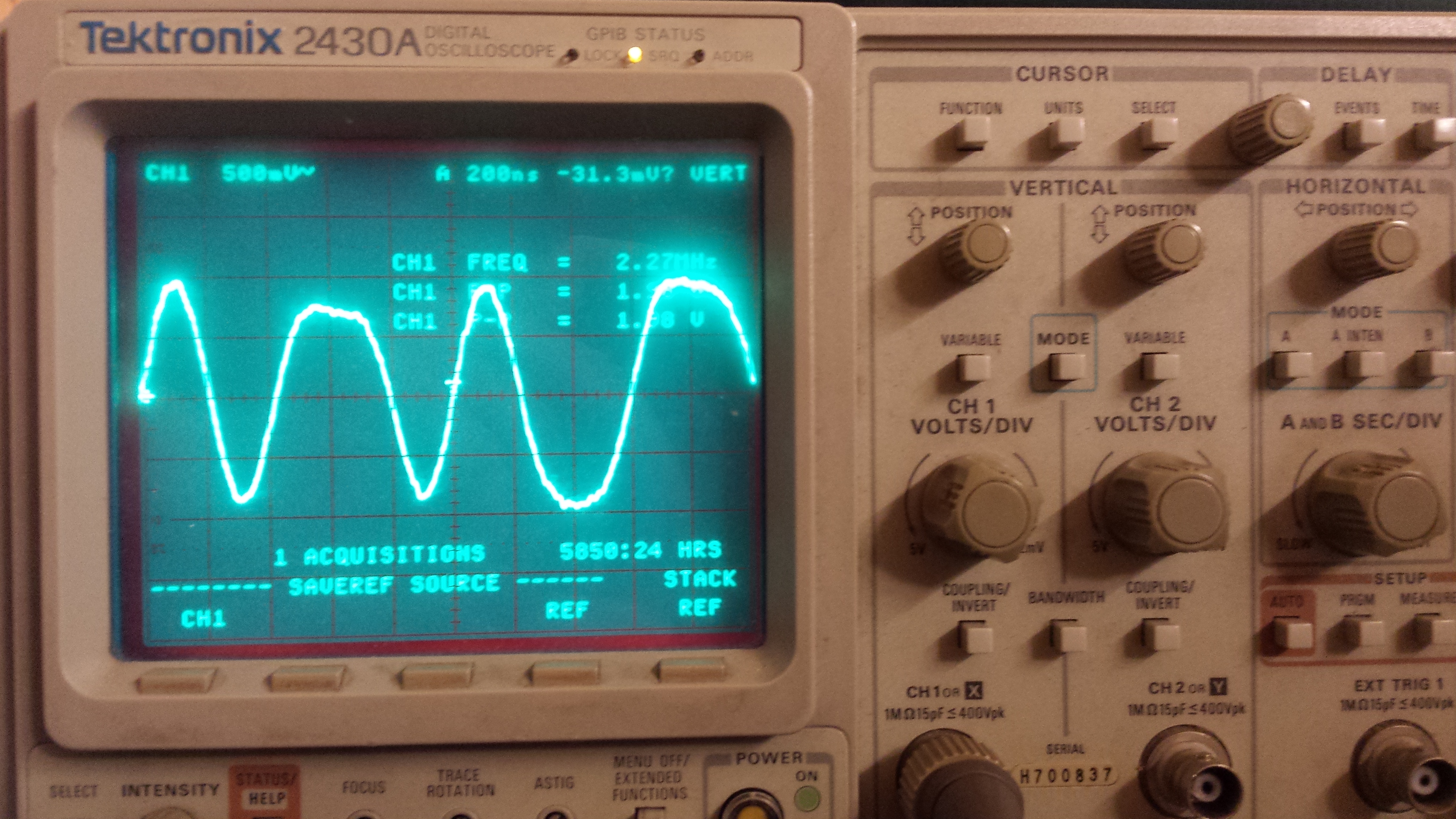
Connecting the oscilloscope to the output of the read amplifier, I can see the data go by. The encoding is very primitive, which makes things easy. One bit-cell takes 400 nanoseconds. If there is a single flux-transition in a cell, it reads as a 0, if there are 2, it reads as a 1. So, on the picture above you can read "10100" from left to right.
- Details
One of my projects is to emulate the Philips X1215 cartridge disc drive (at the drive level, so the emulator connects to the original CDD controller).
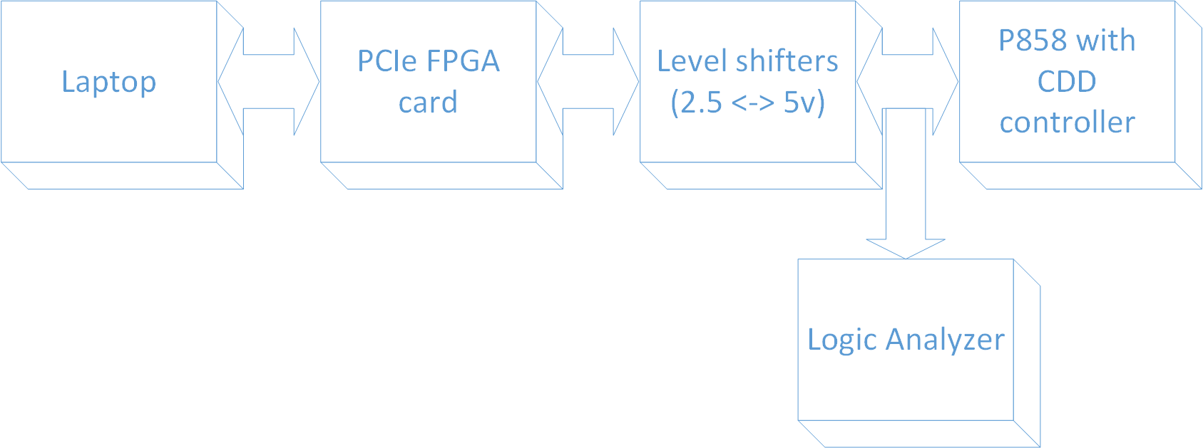
The system consists of a laptop with a special driver and program on it, an FPGA card that is programmed to emulate the disk, some level shifters to provide I/O at the 5 volts level the controller operates at, and a cable to connect the level shifters to the controller. The cable has an extra connector on it to easily attach a logic analyzer for debugging purposes.
The chain between the disk image (sitting on a PC) and the P800 is as follows:
- Disk image on PC
- Disk serving application on PC
- PCIe bus
- FPGA card
- Level converters (3.3v <==> 5v)
- Cable
- CDD X1215 control unit in P800
- P800 CPU
Disk image on PC
The disk image is a binary file that simply contains the data found on a disk pack. So, it's got 2 * 204 * 16 blocks that are each 410 bytes long. Theo Engel has some images available for download from his site.
Disk serving application on PC
This is a fairly simple application that communicates with the FPGA over the PC's PCIe bus. It presents a simple dialog; something like this:
| X1215 DISK SERVER v0.0 Fixed disk? C:\P800\disk0.img Unit off-line, load a cartridge to bring it on-line or type EXIT Cartridge? C:\P800\disk1.img Unit on-line, type YES to take unit off-line Off-line? YES Unit off-line, load a cartridge to bring it on-line or type EXIT Cartridge? C:\P800\disk2.img File does not exist. Do you want to create a new image? YES Unit on-line, type YES to take unit off-line Off-line? YES Unit off-line, load a cartridge to bring it on-line or type EXIT Cartridge? EXIT Bye bye |
Communication with the FPGA is through a 32KB memory range. This range is divided into 4 * 16 512-byte blocks. This is enough to contain all the data for one track on both the fixed and the removable platters at once. This way, the memory only needs to be updated when a SEEK is issued, which the controller expects to take some time.Of course, only 410 bytes out of each 512 byte block are actually used for data. One 32-bit word in the unused area is used for status communication.
<OPERATION
- When the disk serving application starts, it loads the track 0 data into the FPGA, then writes data to the status word to inform the FPGA that a) the disk is online and that b) data has been loaded for track 0.
- If a seek is issued by the control unit, the FPGA signals this to the application by changing the track number to the one needed. If the previous track has been written to, a dirty flag is set in the status word.
- When the application sees the changed track number, it examines the dirty flag. If it is set, the data from the FPGA is read back to the application's copy of the disk images.
- The application now loads the data for the new track into the FPGA. It signals the FPGA by writing the new track number to the status word.
- When the user opts to unload the cartridge, the PC signals the FPGA that the unit goes off-line. It then checks the dirty flag and reads back the track data if needed. It then closes the disk image file after updating it.
FPGA Card
The FPGA card is the heart of the emulated disk drive. It responds to commands from the control unit by instructing the application to perform seeks, selecting the right head, and performing read and write operations. It properly serializes data for reading, and unserializes data for writing. It provides all the necessary timing signals (sector and index pulses) to the control unit.
The FPGA card used is a Xilinx XUPV5.
Level converters
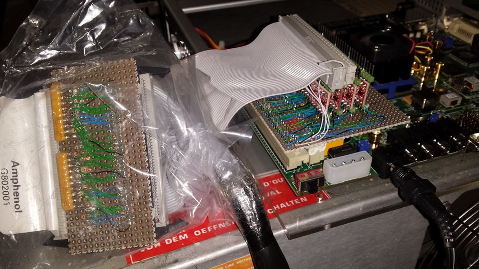
These are necessary because the FPGA uses 3.3 volts for a logic "1", and the control unit uses 5 volts for a logic "1". I'm building a sandwiched interface card that sits on top of the FPGA card, containing 64 level converters (more than is needed here, but I like the flexibility so I can use it for more projects requiring more pins). I'm building it out of perfboard, using wire-wrap technique to connect the converters to the connectors.
Cable
This is a custom-made cable that has a 50-pin IDC connector on one end (to connect to the level converter board), and a 74-pin card edge connector on the other end (to connect to the CDD). Why Philips couldn't use a more common connector size is beyond me!
The cable has also been fitted with two 20-pin IDC connectors for direct connection to my logic analyzer.
P800 and CDD
The P800 and CDD themselves remain completely unchanged. The emulator connects to the CDD the same way a real X1215 would.
- Details